
In my last post I documented the process of getting Node-RED up and running on a Raspberry Pi. In this post I’m going to provide complete instructions for getting a Grid Insight Ledbetter Board, which can read electricity and water meters, set up and running with a Raspberry Pi and Node-RED, uploading meter readings to a remote server.
1. Get a Raspberry Pi
There are all sort of places to get a Raspberry Pi, and any Raspberry Pi will do. But a good kit to buy, which includes everything you need, is the Cana Kit Ultimate, which, at this writing, sells for $89.00 CDN and includes the Pi, a power supply, a wifi dongle, HDMI cable, a breadboard, ribbon cable and T-connector for wiring up the Ledbetter board, and a nice plastic case.
2. Set up the Raspberry Pi
It’s easiest to get up and running if you have an HDMI-capable display, USB keyboard and mouse to connect to the Pi, as well as a wired Ethernet connection to the Internet, at least until you get it set up for wifi.
Plug the ribbon cable into the GPIO slot so that you’re ready to install the Ledbetter Board on the breadboard in a later step.
Insert the SD card into the Pi, connect the HDMI cable, the Ethernet cable, the keyboard and the mouse, and then connect the power supply.
When prompted, install the “Wheezy” distribution from the NOOBS installer.
Once this is installed, and the Pi has rebooted after installation, you’ll end up at the Linux command line, where you can then install a curses-based wifi configuration tool:
sudo apt-get install wicd-curses
You can also set the password for the “pi” user, the time zone and the hostname by running:
sudo raspi-config
Once you’ve done all that, and rebooted the Pi, you can set up wifi with:
wicd-curses
You’ll see a list of wifi SSIDs: find yours and cursor down to it and then cursor-right to set up the wifi password and any other options; be sure to check “Automatically connect to this network” so that this network is connected to automatically every time the Pi reboots. Press F10 to save your settings, then ENTER to connect to the wireless network. The result should look something like this, with your new IP address displayed at the button of the screen:
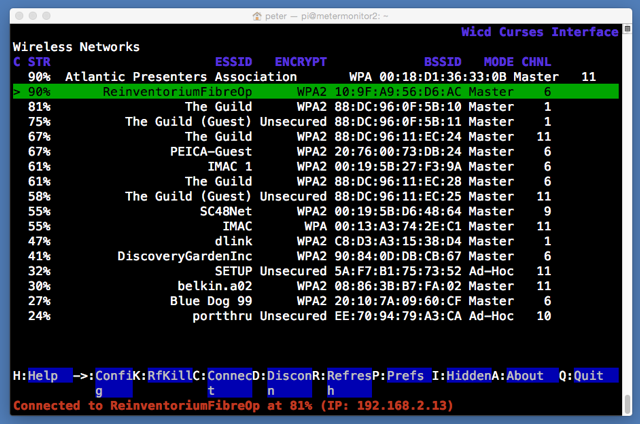
Take note of the IP address your Pi was assigned (mine was 192.168.2.13), and then, from another terminal on the same network (i.e. your laptop or desktop connected to the same wireless network):
ssh -l pi 192.168.2.13
(where you substitute the IP address you were assigned for the 192.168.2.13). You’ll be prompted for the password for the “pi” user: enter the value you selected earlier.
I found the wifi to be more reliable when I modified the power-saving settings:
sudo nano /etc/modprobe.d/8192cu.conf
and paste in:
# Disable power saving
options 8192cu rtw_power_mgnt=0 rtw_enusbss=1 rtw_ips_mode=1
I also found that I needed to disable the ability to login to the Pi via the serial port to get the GPIO connection to the Ledbetter Board working:
sudo nano /etc/inittab
and then comment out the line:
T0:23:respawn:/sbin/getty -L ttyAMA0 115200 vt100
3. Install Node-RED
From the command line of your Pi, once you’ve done all of the above and are logged in, you’re ready to install Node-RED:
wget http://node-arm.herokuapp.com/node_latest_armhf.deb
sudo dpkg -i node_latest_armhf.deb
wget https://github.com/node-red/node-red/archive/0.9.1.zip
unzip 0.9.1.zip
mv node-red-0.9.1 node-red
cd node-red/
npm install --production
The last step will take a while to complete; be patient.
Next install the serial port node for Node-RED:
npm install serialport
And then configure Node-RED to automatically start on bootup:
wget https://gist.githubusercontent.com/Belphemur/cf91100f81f2b37b3e94/raw/72e9a7e779ae343121ce535e312a9872fc9d5fb6/node-red -O /etc/init.d/node-red
sudo chmod +x /etc/init.d/node-red
sudo update-rc.d node-red defaults
Finally, reboot the Pi so that all of the settings take effect:
sudo reboot
4. Install the Node-RED Workflow
Once the Pi has rebooted, you should be able to visit this address in a web browser on a device connected to the same wireless network (substitute the IP address of your Pi for the 192.168.2.13):
http://192.168.2.13:1880
Click on the “hamburger” icon in the top-right of the display, select Import and then Clipboard and paste in the following, substituting the path to a remote REST interface URL for PATH-TO-WEBSERVER-SCRIPT. Place the workflow on the Node-RED canvas with a click, and click DEPLOY to save the workflow.
[
   {
      "id":"e046421c.7b0da",
      "type":"serial-port",
      "serialport":"/dev/ttyAMA0",
      "serialbaud":"9600",
      "databits":"8",
      "parity":"none",
      "stopbits":"1",
      "newline":"\\n",
      "bin":"false",
      "out":"char",
      "addchar":"false"
   },
   {
      "id":"b0910fee.8b01a",
      "type":"csv",
      "name":"parse scm messages",
      "sep":",",
      "hdrin":"",
      "hdrout":"",
      "multi":"one",
      "ret":"\\n",
      "temp":"messagetype,serialnumber,reading,metertype,tampercode,signalstrength",
      "x":500,
      "y":460,
      "z":"5d86b745.52bdc8",
      "wires":[
         [
            "544f7094.a3211"
         ]
      ]
   },
   {
      "id":"544f7094.a3211",
      "type":"function",
      "name":"make url for posting to database",
      "func":"msg.url = \"https://PATH-TO-WEBSERVER-SCRIPT\";\nmsg.url += \"?serialnumber=\" + msg.payload.serialnumber;\nmsg.url += \"&metertype=\" + msg.payload.metertype;\nmsg.url += \"&reading=\" + msg.payload.reading;\nreturn msg;\n",
      "outputs":1,
      "x":638,
      "y":613,
      "z":"5d86b745.52bdc8",
      "wires":[
         [
            "1683d875.a08e3"
         ]
      ]
   },
   {
      "id":"17af58a5.200097",
      "type":"switch",
      "name":"route on message type",
      "property":"payload",
      "rules":[
         {
            "t":"cont",
            "v":"UMSCM"
         },
         {
            "t":"cont",
            "v":"UMIDM"
         }
      ],
      "checkall":"false",
      "outputs":2,
      "x":493,
      "y":363,
      "z":"5d86b745.52bdc8",
      "wires":[
         [
            "b0910fee.8b01a"
         ],
         [

         ]
      ]
   },
   {
      "id":"1683d875.a08e3",
      "type":"http request",
      "name":"post to remote mysql database",
      "method":"GET",
      "url":"PATH-TO-WEBSERVER-SCRIPT",
      "x":618,
      "y":722,
      "z":"5d86b745.52bdc8",
      "wires":[
         [

         ]
      ]
   },
   {
      "id":"8622d22d.68ea8",
      "type":"serial in",
      "name":"Ledbetter Board",
      "serial":"e046421c.7b0da",
      "x":291,
      "y":261,
      "z":"5d86b745.52bdc8",
      "wires":[
         [
            "17af58a5.200097",
            "b262de18.43cc38"
         ]
      ]
   },
   {
      "id":"b262de18.43cc38",
      "type":"debug",
      "name":"",
      "active":true,
      "console":"false",
      "complete":"false",
      "x":604,
      "y":212,
      "z":"5d86b745.52bdc8",
      "wires":[

      ]
   }
]
Here’s a little PHP script that you can use as an starting point for your own archiving of data to a MySQL database:
<?php

if ($_GET) {

    $db = new mysqli("HOST", "USER", "PASSWORD", "DATABASE");

    /* check connection */
    if ($db->connect_errno) {
        printf("Connect failed: %s\n", $db->connect_error);
        exit();
    }

	$query = sprintf("INSERT into readings (serialnumber,datestamp,metertype,reading) values ('%s','%s','%s','%s')",
				mysqli_real_escape_string($db,$_GET['serialnumber']),
				strftime("%Y-%m-%d %H:%M:%S"),
				mysqli_real_escape_string($db,$_GET['metertype']),
				mysqli_real_escape_string($db,$_GET['reading']));

	if (mysqli_query($db, $query) === TRUE) {
		header("HTTP/1.1 201 OK");
	}
	else {
		printf("INSERT failed: %s\n", $db->connect_error);
		exit();
	}
}
5. Set up the Ledbetter Board
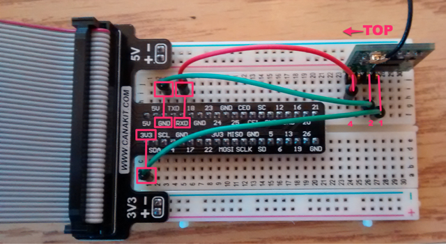
Plug your GPIO ribbon cable adapter into your breadboard as in the photo below.
Snap the pigtail connector for the antenna into the Ledbetter Board, and the slide the board into the breadboard, noting which side is “up” (you can tell by reading the label screen-printed onto the board)
The Ledbetter Board has 4 pins, only 3 of which are used: you need to wired up:
- Pin 1 on the Ledbetter connects to the 3V3 power pin on the Pi
- Pin 2 on the Ledbetter connects to GND (ground) on the Pi
- Pin 4 on the Ledbetter connects to RXD on the Pi
Here’s what my setup looks like when it’s wired up:
6. Watch it Work
Power off the Pi from the terminal:
sudo shutdown now
Then plug the ribbon cable from the Pi into the breadboard connector, and power the Pi back on.
Visit Node-RED in your web browser as above, and click on the Debug tab in your workflow, and you should start to see SCM messages flowing in:
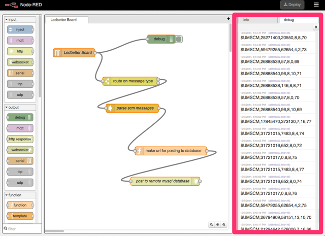
You should also see your database back end filling up with reports.
Troubleshooting
There are many moving parts in this setup, so many opportunities for things that could go slightly wrong. Things that went wrong for me in my various setups that you might want to check:
- Are the proper Ledbetter Board pins wired to the proper GPIO pins? Make sure you’ve got “top” and “bottom” on the board properly oriented: the “top” is the side that has “Ledbetter Board” stencilled on it.
- Are you lined up with the proper GPIO pins on the breadboard?
- Check the “Debug” window in Node-RED: errors in the workflow nodes might be causing problems. Especially check your server-side script to see if it’s receiving messages properly and without generating errors.
About This Blog
 I am Peter Rukavina and this is my blog. I am a writer, letterpress printer, and a curious person.
To learn more about me, read my /now, look at my bio, listen to audio I’ve posted, read presentations and speeches I’ve written, see things I’ve favourited elsewhere, or get in touch (peter@rukavina.net is the quickest way).
I have been writing here since May 1999: you can explore the 25+ years of blog posts in the archive.
![]() You can subscribe to an RSS feed of posts, an RSS feed of comments, an RSS feed of favourites elsewhere, or a podcast RSS feed that just contains audio posts. You can also receive a daily digests of posts by email. I also publish an OPML blogroll.
You can subscribe to an RSS feed of posts, an RSS feed of comments, an RSS feed of favourites elsewhere, or a podcast RSS feed that just contains audio posts. You can also receive a daily digests of posts by email. I also publish an OPML blogroll.
Instagram • YouTube • Vimeo • ORCID • OpenStreetMap • Internet Archive • PEI.art • Drupal • Github.
Add new comment